
6 Channel Audio Mixer Circuit Diagram
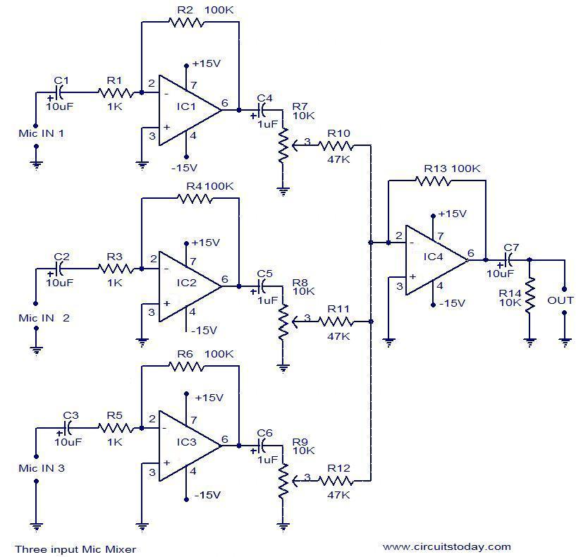
First the three signals (labeled in the diagram) are fed into a summing amplifier. You can add the number of input by adding some components for mixer input (p=10k r=22k).
audio mixer circuit Page 4 Audio Circuits Next.gr
The geheuse is by the way an old german telekom dsl router

6 channel audio mixer circuit diagram. These parts must be wired as shown in the above circuit diagram, connecting r3 and r4 to pin #2 and pin #6 of ic1 for right and left channel respectively. 3 channel audio mixer circuit. Stereo audio mixer the operation stereo audio mixer circuit shown below is straightforward:
The different sounds in songs like the sound of the guitar, drums, the voice of the singer etc. High quality sound mixer schematics wiring diagram circuits schema electronic projects shema. As with any mixer circuit, a slight loss is always introduced.
Only as 6 channel mixer. The stereo audio jack's three pins are numbered on the bottom of the jack. Modular audio mixer with multiple input channels.
Right channel audio is connected to pin 2 and left channel audio is connected to pin 3. Each channel added to the mixer must include the following additional parts: Overall volume of the mixer output.
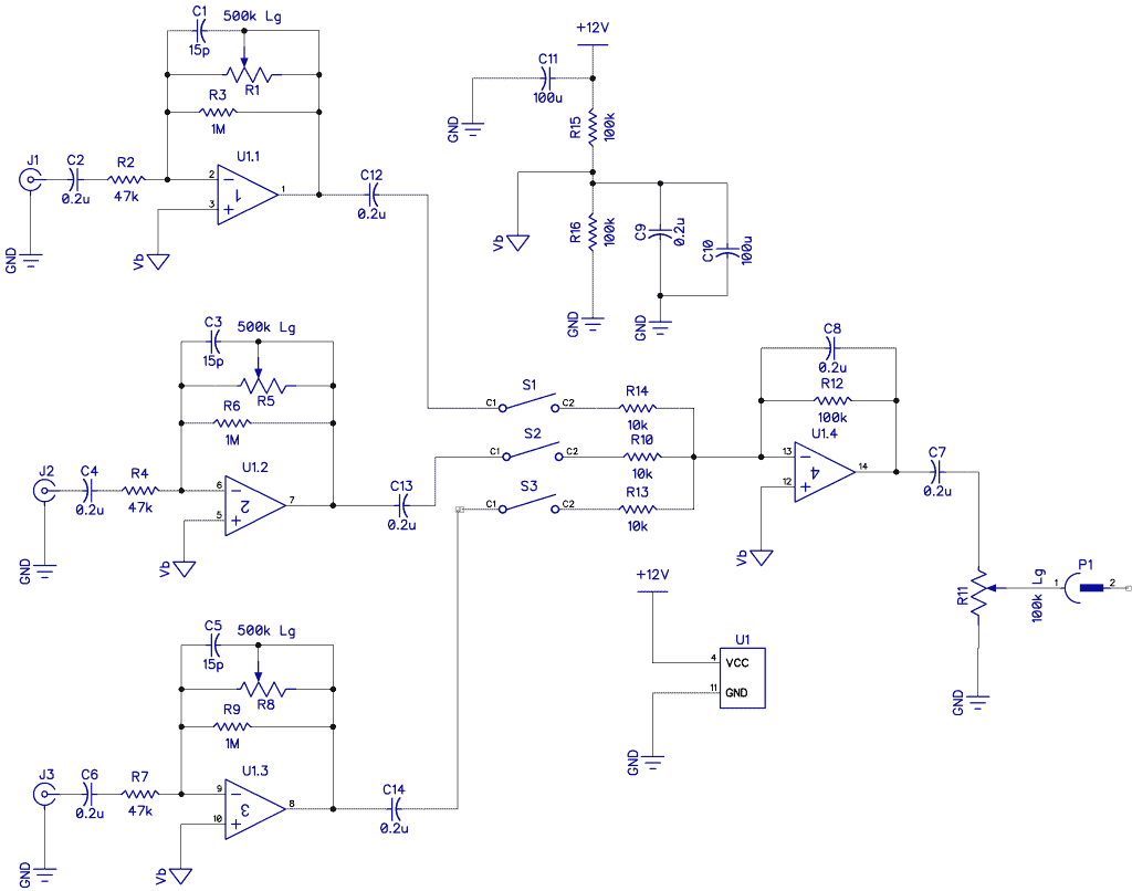
The channels influence each other from the volume. Audio modular mixer with 6 and up channel schematics wiring diagram circuits schema electronic projects. Furthermore, each input level can be trimmed with the help of trimmers pots p4 to p6 to adapt each input to the source.
I want to use as input : 4 channel audio mixer circuit diagram. I want to make a mini 5 channel audio mixer (for home usage).
The explained circuits below are universal simple audio mixer circuits, that may be customized and upgraded to 5 channel or even 10 channel mixers, as desired by the user. This circuit symbol indicates the multiplication aspect of the mixer. Maybe you or someone else have a tip for me on how to fix this.
Gnd is connected to pin 1 and is the longest pin in the middle of the jack. Digital audio mixer use digital signal processing and analog mixers are usually based on operational amplifiers (opamps) electronic circuits. You need build 2 similiar circuits for 2 channel (stereo) audio system.
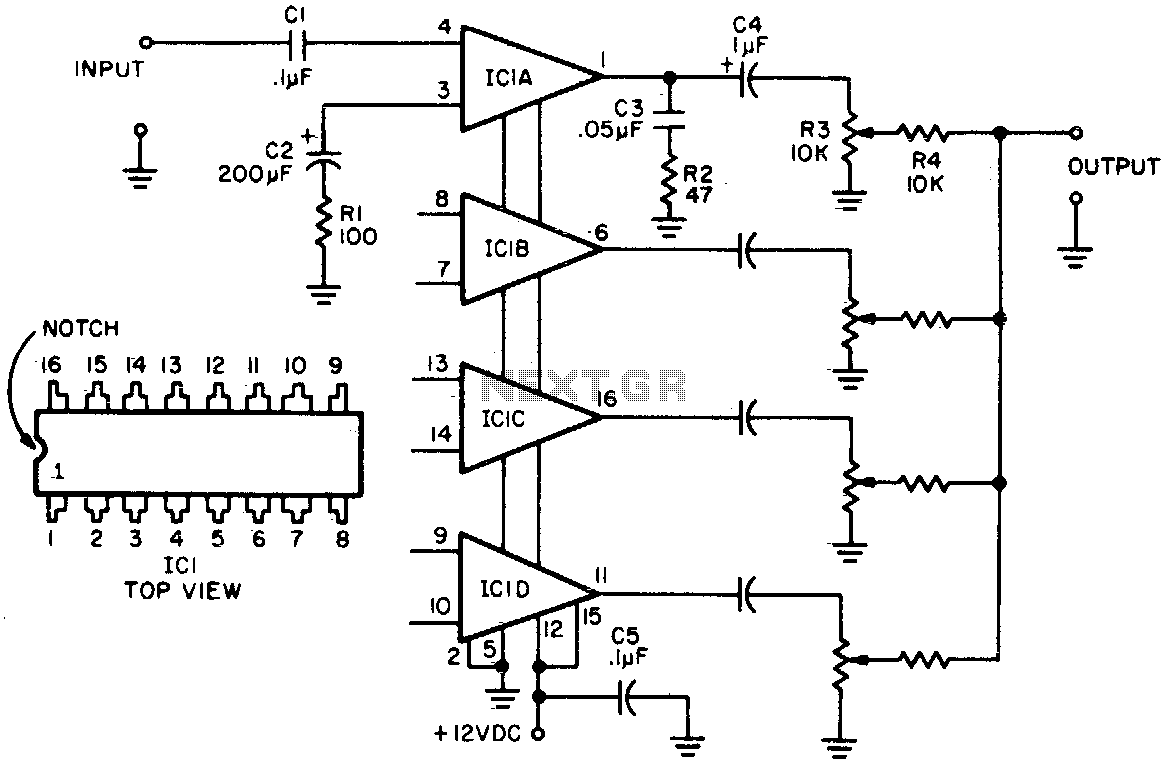
The circuit consists of 4 channel quad amplifier (lm3900). 3.5 mm mono female jack for input. Circuit diagram of multi channel audio mixer using lm3900.
I am a newbie in this section and have a minimum idea of circuit design that's why i am asking for help. Mixer like this ( watch here ) 1) components that i want to use : By adding the same circuit parallel with this, you can increase the number of inputs according to the applications.
Audio modular mixer with 6 and up channel schematics wiring diagram circuits schema electronic projects. Are recorded as separate tracks using separate microphones. I stuck to your circuit diagram only 2 input channels more.
The circuit is for one channel input if you need for example 5 channel mixer then you need to build 5 similar circuits. Audio mixers can be analog or digital type. Two mic audio inputs and two direct line inputs are available in this circuit.
To make audio mixer circuit we need amplifier stage and here lm3900 ic is used as amplifier stage. The input levels can be set by potentiometers p1 or p3. P1, p2, r1, r2, r3, r4, c1 and c2.
Audio modular mixer with 6 and up channel schematics wiring diagram circuits schema electronic projects. You need better mixer circuit for your high class audio system. Fet audio mixer schematics wiring diagram circuits schema electronic projects shema.
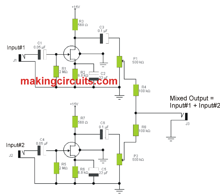
An astonishing feature of this design lies in the fact that a complete stereo mixer as shown below in the block diagram draws less than 6ma current! In the picture below you see the schematic of the whole mixer circuit. So i'll discuss the circuit left to right.
This circuit is only recommend for low and intermediate audio sound system. Unfortunately it's just a bit faulty. Circuit diagram of multi channel audio mixer using lm3900 circuit components:
If a mic is being used, its output is applied to the mic input port of the circuit. This is multi channel audio mixer using main component jfet 2n3819. More than 10 numbers of tracks are very common in normal quality songs.
Probably because i have 6 inputs. First you will need two different sound sources from your laptop to your mixer. An ecm or condenser mic can also be used, but must have bias applied via a series resistor.
This circuit will give only mixed audio output signal with minimum gain and you can use external amplifier to strengthen the audio output signal. Wiring connections the passive mixer circuit consists of four identical audio inputs and one audio output. The mixer circuit below has 3 line inputs and 3 mic inputs.
The audio mixer circuits find its applications in both recording and playback side.

Voltage Controlled Audio Mixer Circuit
audio mixer circuit Audio Circuits Next.gr
51 Surround Sound Circuit Diagram Diagram Media

mic mixer circuit diagram IOT Wiring Diagram

mic mixer circuit diagram IOT Wiring Diagram

My World My Rules Multi Channel Audio Mixer Circuit using


6 Channel Audio Mixer Circuit Diagram AUDIO BARU
mic mixer circuit diagram IOT Wiring Diagram

5 Channel Portable Audio Mixer Audio Mixer schema using

Sound Mixer Circuit Diagram PCB
audio mixer circuit Page 3 Audio Circuits Next.gr
Channel 6 Input Mixer Circuit Automotive_Circuit

6 Channel Audio Mixer Circuit Diagram PCB

MIXER 6+ channel in 2020 Mixer, Electronics projects, Audio
mic mixer circuit diagram IOT Wiring Diagram
What Are Audio Mixers? Circuit Basics

Schematic & Wiring Diagram Audio Mixer 6 Channel circuit
Connecting Mixer To Amplifier Diagram General Wiring Diagram

6 Channel Audio Mixer Electrical Projects, Electrical
