Esser Smoke Detector Wiring Diagram
Collection of carrier air conditioner wiring diagram. This is because fire alarm control.

Esser Smoke Detector Wiring Diagram
Esser smoke detector wiring diagram.

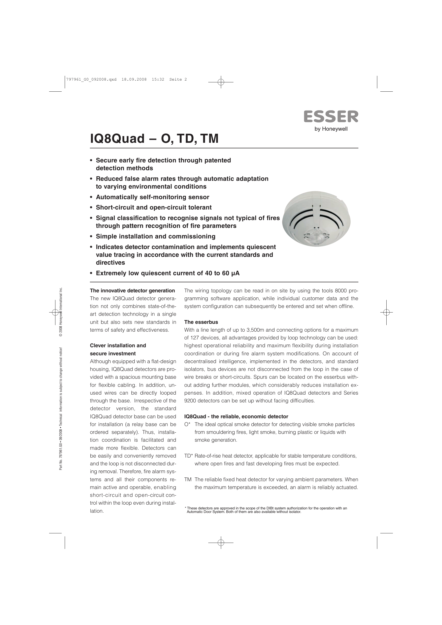
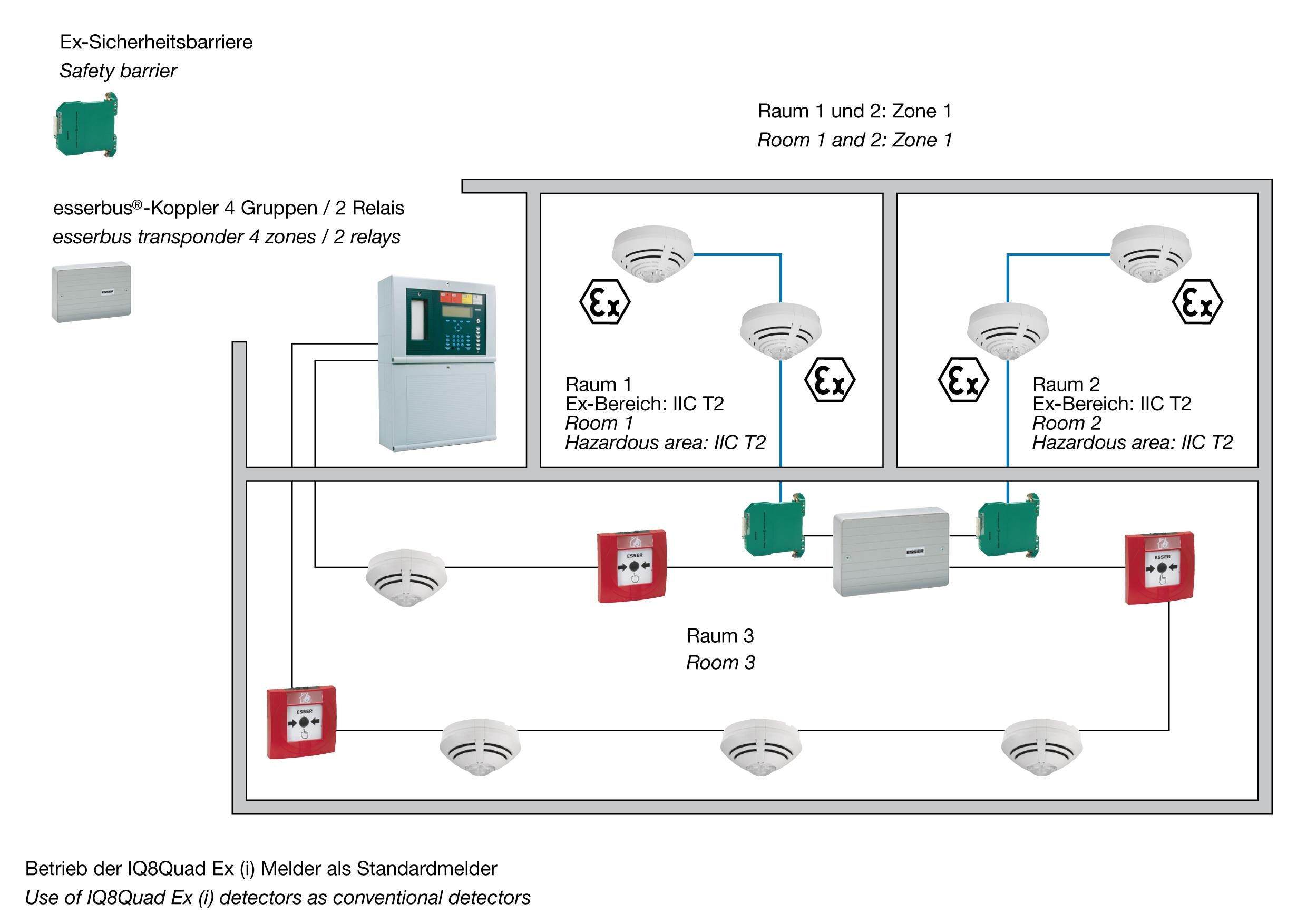
Esser smoke detector wiring diagram. For details on connecting smoke detectors and other devices to a typical alarm panel, see ademco vista 20p wiring diagram. Esser smoke detector wiring diagram easywiring. Esser by honeywell 802371 optical smoke detector guarantees safe and early detection of fire.
Each smoke detector is provided with a standard form a/formc relay for alarm and auxiliary functions. Esser smoke detector wiring diagram wiring diagram honeywell accenta 6 manual introduction to fire alarms 13 four wire smokes with onboard relay installation instruction fire alarm control panel iq8control c m esser catalogue power supply security alarm fire detection systems fire alarm nivo boyut manualzz com. Optical smoke detector which works using the light scatter principle to guarantee safe and early detection of fire.
Check field power leads l1 and l2. The main supply is 120v ac in us and 230v ac in eu. Esser tools 8000 programming softwarecan be used for programming esser fire alarm control panels such as iq8 control m, iq8 control c,â.
In our basic wiring diagram, a single or multiple heat and smoke detectors are installed in the home by connecting the live (line or hot), neutral, ground and an interconnected wire to the alarm. Honeywell esser fire alarm control panel compact manual online: Esser smoke detector base wiring diagram.
In our basic wiring diagram a single or multiple heat and smoke detectors are installed in the home by connecting the live line or hot neutral ground and. The 8000 series smoke detector is an open area photoelectric system smoke detector, engineered to provide reliable early warning against smoke. Supply with 805590 base plate + £4.06 £4.87.
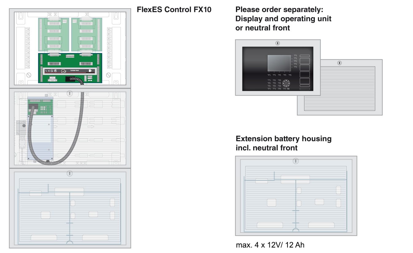
Fire alarm control panel iq8control c/m 2 fb 798951.10.gb0 / 01.10 intended purpose this product must only be used for the applications outlined in the catalogue and the technical description and in combination with external components and systems which have been approved or recommended by esser by honeywell. Mount smoke detectors at least 4 inches from wall or on the wall with the top of the detector within 4 inches and 12 inches of the highest point of the ceiling. Typical household smoke alarms use a black wire for detecting smoke, a white wire as the common conductor and a red wire that communicates with other smoke d.
The main supply is 120v ac in us and 230v ac in eu. For us installations it is typically a short. A smoke or heat detector can be installed to the existing or new home wiring.
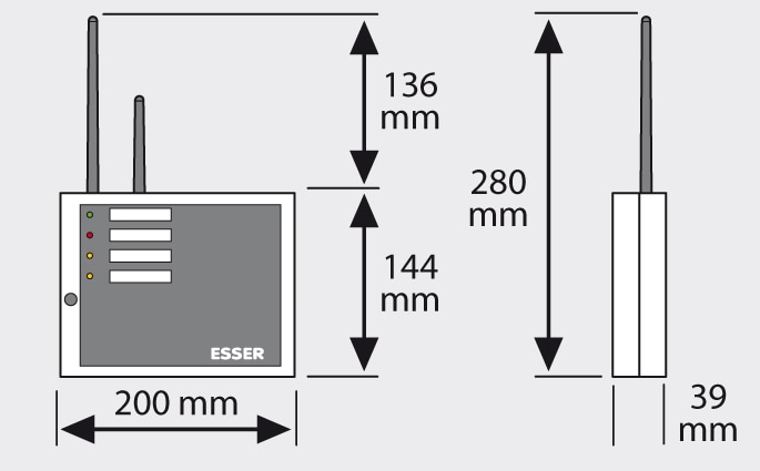
The external power supply for the system is connected via the esserbus ® transponder and can be monitored for trouble. The optical smoke detector works using the light scatter principle to guarantee safe and early detection of fires. The smoke can block or obscure the beam.
Supply with 805590 base plate 406 487. 1.1.3 wiring vesda vlc / lrs compact via the esserbus ® transponder (part no. The new esser product catalogue for fire alarm systems provides detailed information on our portfolio.
Honeywell security and fire, is a. This is the basic fire alarm system used in household wiring. 3a fan coil printed circuit board 3.
Fire alarm wired photoelectric smoke detector. In our basic wiring diagram a single or multiple heat and smoke detectors are installed in the home by connecting the live line or hot neutral ground and an. There are three main parts in the metal detector circuit.
Esser smoke detector wiring diagram. A wiring diagram is a simplified traditional pictorial depiction of an electrical circuit. Wire should be connected to pin.
A hardwired smoke alarm installation involves wiring one of the smoke detectors (closest to the voltage source) to a 120 vac breaker in the main electric panel or tapping from a 120 v electrical box, wiring it using a 14/2 cable with a black (live), a white (neutral), and a ground wire, as shown by the diagram in figure 5. From fire alarm control panels and fire/smoke detectors, to manual call points and more, these systems provide uninterrupted fire protection. Power for the device is supplied on one pair of wires, or loop, while the detection circuit is connected to a second pair.
Alarm.panel wiring diagram gst 5000 fire alarm panelgst addressable smoke detector wiring diagram.central battery system testingâ. This is the basic fire alarm system used in household wiring. The cable runs from the main panel, and connects to each smoke detector in the system.
Esser Fire Alarm Wiring Diagram

Esser Fire Alarm Wiring Diagram
Esser Fire Alarm Wiring Diagram

Esser Fire Alarm Wiring Diagram

Esser Fire Alarm Wiring Diagram

Esser Fire Alarm Wiring Diagram

Esser Fire Alarm Wiring Diagram
Esser Fire Alarm Wiring Diagram
Esser Fire Alarm Wiring Diagram

Esser Fire Alarm Wiring Diagram
Esser Fire Alarm Wiring Diagram

Esser Fire Alarm Wiring Diagram
Esser Fire Alarm Wiring Diagram

Esser Fire Alarm Wiring Diagram

Esser Fire Alarm Wiring Diagram

Esser Fire Alarm Wiring Diagram
Esser Fire Alarm Wiring Diagram


